Capacitors
After studying this section you should be able to:
- describe the action of a capacitor and calculate the charge stored
- relate the energy stored in a capacitor to a graph of charge against voltage
- explain the significance of the time constant of a circuit that contains a capacitor and a resistor
The action of a capacitor
Capacitors store charge and energy. They have many applications, including smoothing varying direct currents, electronic timing circuits and powering the memory to store information in calculators when they are switched off.
A capacitor consists of two parallel conducting plates separated by an insulator.
When it is connected to a voltage supply charge flows onto the capacitor plates until the potential difference across them is the same as that of the supply. The charge flow and the final charge on each plate is shown in the diagram.
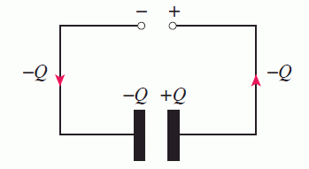
When a capacitor is charging, charge flows in all parts of the circuit except between the plates.
As the capacitor charges:
- charge –Q flows onto the plate connected to the negative terminal of the supply
- charge –Q flows off the plate connected to the positive terminal of the supply, leaving it with charge +Q
- the capacitor plates always have the same quantity of charge, but of the opposite sign
- no charge flows between the plates of the capacitor.
Capacitance
The capacitor shown in the diagram above is said to store charge Q, meaning that this is the amount of charge on each plate. When a capacitor is charged, the amount of charge stored depends on:
- the voltage across the capacitor
- its capacitance: i.e. the greater the capacitance, the more charge is stored at a given voltage.
KEY POINT - The capacitance of a capacitor, C, is defined as:

Where Q is the charge stored when the voltage across the capacitor is V. Capacitance is measured in farads (F). 1 farad is the capacitance of a capacitor that stores 1 C of charge when the p.d. across it is 1 V.
As the capacitor plates have equal amounts of charge of the opposite sign, the total charge is actually zero. However, because the charges are separated they have energy and can do work when they are brought together.
One farad is a very large value of capacitance. Common values of capacitance are usually measured in picofarads (1 pF = 1.0 × 10⁻¹² F) and microfarads (1 μF = 1.0 × 10⁻⁶ F).
Combining capacitors
Like resistors, capacitors can be connected in series or parallel to achieve different values of capacitance.
When capacitors in series are connected to a voltage supply:
- no matter what the value of its capacitance, each capacitor in the combination stores the same amount of charge, since any one plate can only lose or gain the charge gained or lost by the plate that it is connected to
- the total charge stored by a series combination is the charge on each of the two outer plates and is equal to the charge stored on each individual capacitor
- because the applied potential difference is shared by the capacitors, the total charge stored is less than the charge that would be stored by any one of the capacitors connected individually to the voltage supply.
The effect of adding capacitors in series is to reduce the capacitance. When an additional capacitor is added, there is less p.d. across each one so less charge is stored.
The diagram shows the charge on the plates of three capacitors connected in series.
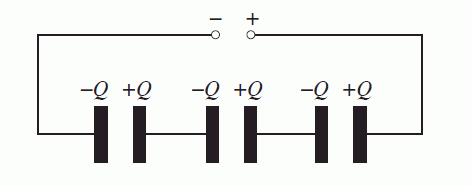
This results in the effective value of a series combination of capacitors being smaller than the lowest value capacitor in the combination.
KEY POINT - The capacitance, C, of a number of capacitors connected in series is given by the expression:

A common error when using this relationship is to forget to carry out the final reciprocation, giving an answer which is equal to 1/C instead of C.
In contrast to this, the effect of connecting capacitors in parallel is to increase the capacitance so that the effective value of a number of capacitors in parallel is always greater than the largest value of the combination.
When capacitors are connected in parallel:
- all the capacitors are charged to the same potential difference
- each capacitor stores the same amount of charge as it would if connected on its own to the same voltage
- adding an additional capacitor increases the total charge stored.
KEY POINT - The capacitance, C, of a number of capacitors connected in parallel is given by the expression: C = C1 + C2 + C3
The expressions for capacitors connected in series and parallel are similar to those for resistors, but the other way round.
The energy stored in a capacitor
Energy is needed from a power supply or other source to charge a capacitor. A charged capacitor can supply the energy needed to maintain the memory in a calculator or the current in a circuit when the supply voltage is too low.
The amount of energy stored in a capacitor depends on:
- the amount of charge on the capacitor plates
- the voltage required to place this charge on the capacitor plates, i.e. the capacitance of the capacitor.
The graph below shows how the voltage across the plates of a capacitor depends on the charge stored.
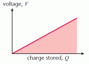
When a charge ΔQ is added to a capacitor at a potential difference V, the work done is ΔQV. The total work done in charging a capacitor is ΣΔQV.
The shaded area between the graph line and the charge axis represents the energy stored in the capacitor.
KEY POINT - The energy, E, stored in a capacitor is given by the expression E = ½ QV = ½CV 2 where Q is the charge stored on a capacitor of capacitance C when the voltage across it is V.
Charging and discharging a capacitor
When a capacitor is charged by connecting it directly to a power supply, there is very little resistance in the circuit and the capacitor seems to charge instantaneously. This is because the process occurs over a very short time interval.
Placing a resistor in the charging circuit slows the process down. The greater the values of resistance and capacitance, the longer it takes for the capacitor to charge.
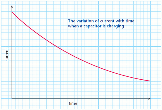
The diagram below shows how the current changes with time when a capacitor is charging.
Having a resistor in the circuit means that extra work has to be done to charge the capacitor, as there is always an energy transfer to heat when charge flows through a resistor.
This graph shows that:
- the charging current falls as the charge on the capacitor, and the voltage across the capacitor, rise
- the charging current decreases by the same proportion in equal time intervals.
The second bullet point shows that the change in the current follows the same pattern as the activity of a radioactive isotope. This is an example of an exponential change, the charging current decreases exponentially.
The graph shown above can be used to work out the amount of charge that flows onto the capacitor by estimating the area between the graph line and the time axis. Since current = rate of flow of charge it follows that:
KEY POINT - On a graph of current against time, the area between the graph line and the time axis represents the charge flow.
To calculate the charge flow:
- estimate the number of whole squares between the graph line and the time axis
- multiply this by the ‘charge value’ of each square, obtained by calculating ΔQ × Δt for a single square.
The time constant
When a capacitor is charging or discharging, the amount of charge on the capacitor changes exponentially. The graphs in the diagram show how the charge on a capacitor changes with time when it is charging and discharging.
Graphs showing the change of voltage with time are the same shape. Since V = Q/C , it follows that the only difference between a charge–time graph and a voltage–time graph is the label and scale on the y-axis.
These graphs show the charge on the capacitor approaching a final value, zero in the case of the capacitor discharging, but never quite getting there.
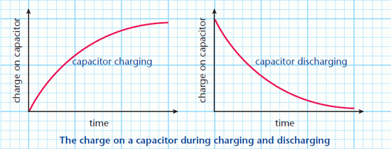
The rate at which the charge on a capacitor changes depends on the time constant of the charging or discharging circuit.
KEY POINT - The time constant, τ, of a capacitor charge or discharge circuit is the product of the resistance and the capacitance:
τ = RC . τ is measured in s.
The greater the values of R and C the longer the charge or discharge process takes. Knowledge of the values of R and C enables the amount of charge on a capacitor to be calculated at any time after the capacitor has started to charge or discharge. This is useful in timing circuits, where a switch is triggered once the charge, and therefore p.d., has reached a certain value.
The time constant τ represents:
- the time it takes for the charge on a capacitor to fall to 1/e of its initial value when a capacitor is discharging
- the time it takes for the charge on a capacitor to rise to 1– 1/e of its final value when the capacitor is charging
The role of the time constant is similar to that of half-life in radioactive decay. When a capacitor is discharging, 1/e2 of the initial charge remains after time 2τ and 1/e3remains after 3τ.
The exponential function e is used to calculate the charge remaining on a capacitor that is discharging.
KEY POINT - The charge, Q, on a capacitor of capacitance C, remaining time t after starting to discharge is given by the expression Q = Q0e–t /τ where Q0 is the initial charge on the capacitor.
Here e is the exponential function, the inverse of natural log, ln. Take care not to confuse this with the EXP button on a calculator, which is used for entering powers of 10.
This expression shows that when t is equal to τ, i.e. after one time constant has elapsed, the charge remaining is equal to Q0e–1, or Q0/e
PROGRESS CHECK
