Magnetic fields
After studying this section you should be able to:
- describe the magnetic fields inside a solenoid and around a wire when current passes in them
- understand the meaning of magnetic field strength
- calculate the size and direction of the force that acts on a current in a magnetic field
This section covers the following topics
Magnetic fields:
- are due to permanent magnets and electric currents
- affect permanent magnets and electric currents.
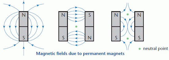
Like other fields, magnetic fields are represented by lines with arrows. The arrows show the direction of the force at any point in the field. The convention when drawing magnetic fields is that the arrows show the direction of the force that would be exerted on the N-seeking pole of a permanent magnet placed at that point.
Although the field lines are often curves, the force at any point acts in a straight line.
The diagrams show the field patterns around a bar magnet and between two different arrangements of pairs of magnets. Where equal-sized forces act in opposite directions, the result is a neutral point. At a neutral point, the resultant magnetic force is zero.

How many forces act on a N-seeking pole placed at the neutral point shown in the middle diagram?
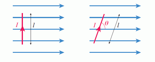
A current-carrying wire placed in a magnetic field experiences a force provided that it is not parallel to the field. The force has its maximum value when the current is perpendicular to the field. Fleming’s left hand rule shows the direction of the force on any current that has a component which is perpendicular to a magnetic field. The diagram illustrates Fleming’s rule and its application to a simple motor.

The force on any electric current that is parallel to a magnetic field is zero – there is no force.
In electric and gravitational fields, the strength of the field is defined in terms of the force per unit mass or charge. There is no obvious equivalent ‘unit of magnetism’.
The size of the force on a current-carrying conductor in a magnetic field depends on:
- the size of the current
- the length of conductor in the field
- the orientation of the conductor relative to the field
- the strength of the magnetic field.
These factors are used to define the ‘unit’ of magnetism as current length, the product of the current and the length of the conductor in the field.
KEY POINT - These factors are used to define the strength of a magnetic field as: the force per unit (current × length) perpendicular to the field. Magnetic field strength is also known as flux density. Its symbol is B and the unit is the tesla (T).
With the current and magnetic field directions shown in the diagram below the force is into the paper.

KEY POINT - The force on a current-carrying conductor in a magnetic field is given by the expressions: when the conductor is perpendicular to the field lines: F = BIl when the angle between the conductor and the field lines is θ, F = BIlsinθ
You should always specify the directions of the quantities when using these relationships to define magnetic field strength.
These relationships, together with the diagrams, can be used to define magnetic field strength.
Any moving charge constitutes an electric current. In a vacuum tube, such as that in a television or a cathode ray oscilloscope, magnetic fields are used to exert forces on the electrons as they travel through the tube.
The size of the force on a charged particle moving in a magnetic field depends on:
- the charge on the particle
- the speed of the particle
- the strength of the magnetic field.
For a charge Q moving with velocity v, the equivalent of (current × length) is (charge × velocity) or Qv.
KEY POINT - A charge Q moving with velocity v perpendicular to a magnetic field experiences a force: F = BQv
The direction of the force is given by Fleming’s left hand rule.
PROGRESS CHECK

