Series and Parallel Circuits
This section explains series and parallel circuits covering, series circuits, total resistance, and the total resistance equation, parallel circuits and the key differences between series and parallel circuits.
Series Circuits
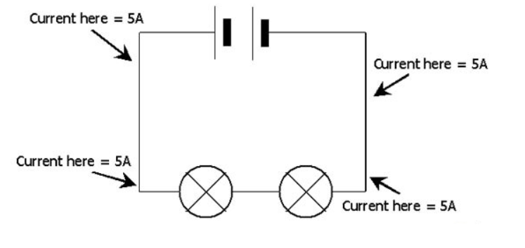
A series circuit is a type of electrical circuit where all components are connected end-to-end in a single loop. In a series circuit, the current flows through every component one after another.

- Current: The current is the same at all points in a series circuit. This is because there is only one path for the current to flow.
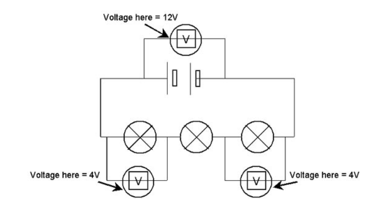
- Voltage: The total voltage across the circuit is shared between the components. The sum of the voltages across each component equals the total voltage from the power supply.
- Resistance: The total resistance in a series circuit is the sum of the individual resistances of each component. This means that adding more resistors in series increases the total resistance of the circuit.
Total Resistance (Rₜₒₜₐₗ) = R₁ + R₂ + R₃ + ...
Where:
- R₁, R₂, R₃, ... are the resistances of the individual components.
Total Resistance Equation
In a series circuit, the total resistance is always greater than any individual resistance. For example, if you have two resistors in series, one with a resistance of 2 ohms and another with 3 ohms, the total resistance would be:
Rₜₒₜₐₗ = 2Ω + 3Ω = 5Ω
This principle holds true no matter how many resistors you add in series. The more resistors, the higher the total resistance.
Parallel Circuits
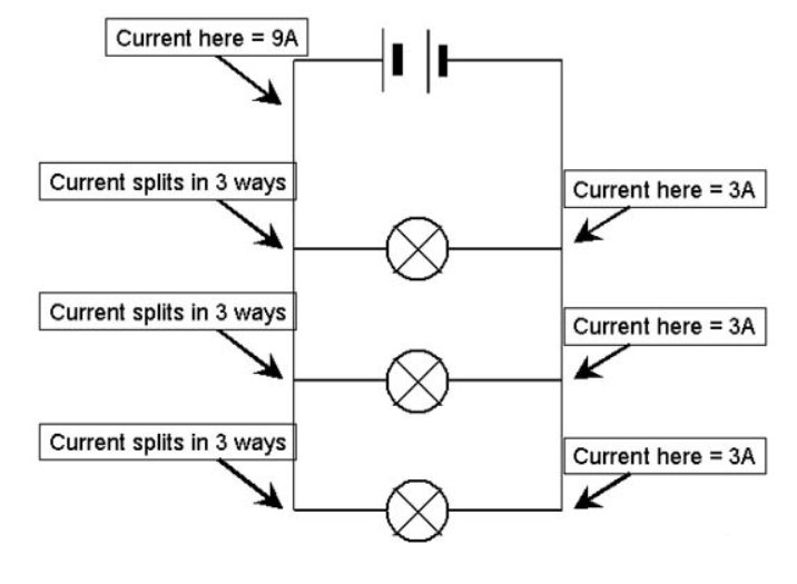
A parallel circuit is a type of electrical circuit where the components are connected in separate branches. Each component has its own individual path to the power supply.

- Current: The total current in a parallel circuit is the sum of the currents through each branch. Each branch can carry a different current depending on its resistance.
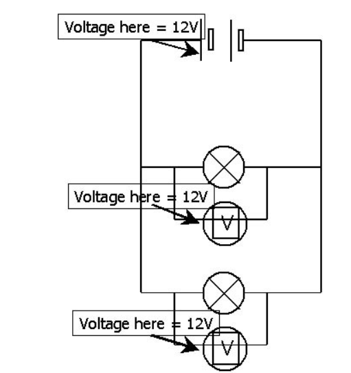
- Voltage: The voltage across each branch in a parallel circuit is the same as the voltage from the power supply. All components in parallel experience the same potential difference.
- Resistance: The total resistance in a parallel circuit is less than the resistance of the smallest individual resistor. As you add more resistors in parallel, the total resistance decreases.
Total Resistance (Rₜₒₜₐₗ) = 1 / (1/R₁ + 1/R₂ + 1/R₃ + ...)
Where:
- R₁, R₂, R₃, ... are the resistances of the individual components.
Example: Total Resistance in a Parallel Circuit
If you have two resistors in parallel, one with a resistance of 4 ohms and the other with a resistance of 6 ohms, you can calculate the total resistance using the formula:
$$\frac{1}{Rₜₒₜₐₗ} = \frac{1}{4Ω} + \frac{1}{6Ω}$$
$$\frac{1}{Rₜₒₜₐₗ} = \frac{3}{12} + \frac{2}{12} = \frac{5}{12}$$
Now, invert to find the total resistance:
$$Rₜₒₜₐₗ = \frac{12}{5} = 2.4Ω$$
So, the total resistance is 2.4 ohms, which is lower than either of the individual resistances.
Key Differences Between Series and Parallel Circuits:
| Aspect | Series Circuit | Parallel Circuit |
|---|---|---|
| Current | Same throughout the circuit | Divided between branches |
| Voltage | Shared between components | Same across each component |
| Total Resistance | Sum of individual resistances | Less than the resistance of the smallest component |
| Effect of Adding Resistors | Increases total resistance | Decreases total resistance |


Series circuits have components connected in a single loop, which leads to a higher total resistance and the same current flowing through all components. On the other hand, parallel circuits allow multiple paths for the current, with a lower total resistance and the same voltage across each branch.
Understanding these fundamental differences between series and parallel circuits will help you solve various problems in GCSE Physics and understand how electrical systems work in everyday life.
