Moments, Levers, and Gears
This section explains moments, levers and gears covering, moment of a force formula, principle of levers and gear systems.
Moments
A moment is the turning effect of a force about a pivot point. It is responsible for rotating an object around a fixed point. Moments are an important concept in understanding how levers, gears, and other mechanical systems work.
Image
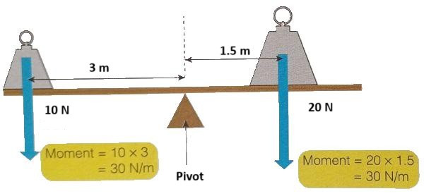
The size of the moment depends on two factors:
- The force applied.
- The distance from the pivot point (also known as the moment arm or lever arm).
Moment of a Force Formula
The moment of a force is calculated using the formula:
$$\text{Moment (M)} = \text{Force (F)} \times \text{Distance (d)}$$
Where:
- M is the moment in Newton-metres (N·m).
- F is the force applied in Newtons (N).
- d is the perpendicular distance from the pivot point to the line of action of the force in metres (m).
Example:
If a force of 10 N is applied to a spanner 0.3 metres from the pivot point, the moment can be calculated as:
$$M = F \times d$$
$$M = 10 \, \text{N} \times 0.3 \, \text{m}$$
$$M = 3 \, \text{N·m}$$
So, the moment is 3 Newton-metres (N·m).
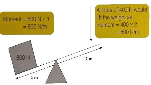
Levers
A lever is a simple machine that uses a rigid bar (or beam) to amplify a force. It consists of:
- A pivot (also known as the fulcrum),
- A load (the object being moved or lifted),
- A force (the effort applied to move the load).
There are three types of levers, depending on the relative positions of the load, pivot, and effort:
Image
First-class lever: The pivot is between the load and the effort (e.g., a see-saw).
Second-class lever: The load is between the pivot and the effort (e.g., a wheelbarrow).
Third-class lever: The effort is between the pivot and the load (e.g., a pair of tongs).
The mechanical advantage of a lever is calculated by the ratio of the distance from the pivot to the effort (effort arm) to the distance from the pivot to the load (load arm).
Principle of Levers
The principle of levers is based on the fact that, for rotational equilibrium (no turning), the sum of moments about the pivot point must be zero. This is expressed as:
$$\text{Moment of Effort} = \text{Moment of Load}$$
$$F_{\text{effort}} \times d_{\text{effort}} = F_{\text{load}} \times d_{\text{load}}$$
Where:
- Fₑ is the force (effort),
- dₑ is the distance from the pivot to the effort,
- Fₗ is the load force,
- dₗ is the distance from the pivot to the load.
Gear Systems
A gear system is a set of gears working together to transfer rotational motion and force from one part of a machine to another. Gears consist of toothed wheels that interlock with each other. When one gear turns, it causes the others in the system to turn as well.
Key Concepts of Gear Systems
- Input gear: The gear to which force is applied.
- Output gear: The gear that receives the force and moves the load.
- The teeth on the gears allow them to interlock and transmit force.
Gear Ratios
The ratio of the number of teeth on two meshing gears determines the mechanical advantage and the change in speed or torque (turning force).
- If the input gear has more teeth than the output gear, the output gear will rotate faster, but with less force.
- If the input gear has fewer teeth than the output gear, the output gear will rotate slower, but with greater force.
Example of Gear Systems:
- Small gear driving a large gear: The smaller gear will rotate faster than the larger gear but will provide less force.
- Large gear driving a small gear: The larger gear will rotate more slowly but will exert greater force.
Moments describe the turning effect of a force, and their size is determined by both the force applied and the distance from the pivot point. Levers are simple machines that use moments to amplify force, with different types based on the positions of the load, effort, and pivot. Gear systems allow for the transmission of rotational force and can change the speed or force of rotation depending on the gear sizes and ratios. Understanding these concepts is crucial for mastering mechanical systems and the application of forces in GCSE Physics.
Category